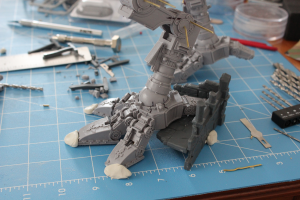
titan

All posts tagged titan

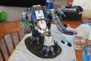
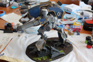
Finished at last! I give you Lupus Persequens (a rough translation of Stalking Wolf).

warhoundCompleteFront1 warhoundCompleteSide

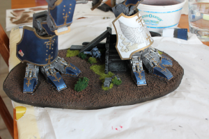
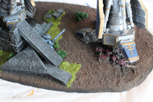
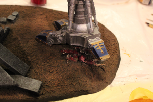
Here you can see the results on the base. That Fire Warrior is thinking “Right, so… staying right here, then.”

warhoundBaseDetailFront titanBaseCompleteTauChaosCloseup

Apologies for blurriness in the middle sections of these pictures below; I was having a hard time getting my wife’s fancy camera to focus on the parts I wanted.

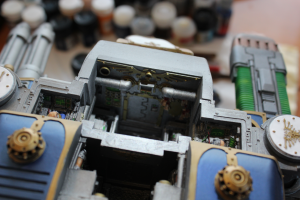
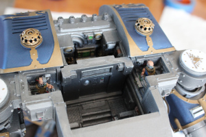
mainBodyInteriorFront mainBodyInteriorRear

For final assembly, I epoxied the head onto the body (drilled a couple of small grab-holes into the head socket and and head’s ball joint), then let it dry overnight while I epoxied the remaining leg armor and the pelvic plate into place. Lastly, I drilled a few grab-holes into the waist junction, on both sides, and then slathered some JB Weld onto it, and let it dry over night; no clamping was needed since the balance was good enough to allow it to just sit on there in the pose I wanted.

epoxyingHeadToBody

Here’s some more details on the final stages of base finishing. I wanted to have an infantry model on the base to give a sense of scale for when the titan isn’t being used in a game (because, let’s be honest, I’m probably going to get to use this only a very few times, so it’s mostly going to be for display). One of my friends suggested I should have someone getting stepped on, like a Tau Crisis Suit or something, but there were a couple of problems with that in my mind. Firstly, I don’t like super gory models and bases. Personal opinion, but I just don’t think they look good, and I don’t particularly want something like that in my house where my 1 year-old is going to ask questions about what all that blood spilling out of the squashed guy is. Secondly, I kind of like the Tau and am considering them as a second army (My main is Space Marines), so I don’t necessarily want to run into a situation where I’m fielding this thing alongside a potential future Tau army and there’s squashed Tau guys under the Titan. Awkward… I thought about doing a Fire Warrior standing by the ruins looking scared, but that can be hard to convey with a model sometimes (my green stuff skills are not amazing). But then I thought, maybe I could have the Fire Warrior watching somebody get stepped on– that would convey the general feeling.

Anyway, I got to thinking that if I wanted anybody to be stepped on, it’d be Chaos. I don’t think I’m ever going to field a Chaos army, and they’ve kind of been my arch-nemesis ever since I started playing 40k (both my brother and my high school friends played Chaos armies). So, I decided I could do a squashed Chaos marine and wouldn’t need to make him all gory to get the point across that “this guy just got stepped on by something enormous.”

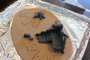
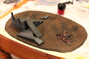
In this first picture you can see that I had remarked the toe positions in a darker marker; this makes it possible for me to slather gluey sand all over the base without getting it all over the toes of the titan. In the below picture, the ruins behind the titan’s left foot and the tile pieces behind that have all been epoxied in place. I’ve also glued down the Chaos posessed marine that’s been smashed into the ground. I bent his arms and backpack up a bit, then smashed his shoulder pads with a clamp I had used earlier in the titan-building process.

squashedChaosBaseGlued

Next up, I put down some sand. For this, I basically just dumped some sand into a plastic cup and added water until the sand looked wet and was easily stir-able without being too much like slime. Then I added a bunch of PVA glue and spread it onto the base with a plastic spoon and a knife to give me a bit more precision. After it had dried, it was pretty solid, so I spray-primed the whole thing black, then dry-brushed brown over the dirt with a large brush. After that, I did some drybrushed P3 Greatcoat Grey and Citadel Administratum Grey onto the ruins and stones. I think I followed it up with a very light drybrushing of Dheneb Stone, but I don’t quite remember. I also did a lighter brown on the dirt in some places for highlights. I didn’t bother doing a wash; I tried it a bit on a small area and it was almost completely invisible, so I didn’t bother with doing any more. I did the Chaos marine in red so he’d stand out from the blue on the titan and brown on the base. I also washed him liberally with Agrax Earthshade to give him more of a beat-up and dirty look.

squashedChaosBasePainted

Here you can see it with the titan’s legs placed over the body while I was checking what it would look like when finished.

squashedChaosWithFoot

Next up, completed titan!

It’s been a little while since I posted, but I’ve made a lot of progress; it’s been rather slow, but relatively consistent. I started final assembly of the titan today. The legs are epoxied to the base and are curing as I write, the rest of the titan will follow suit over the course of the next few days. I have to leave 16-24 hours for drying time between each stage.

Since I started off talking about the base in the last post, I’ll lead off talking about it here as well. After doing some of the painting I demonstrated at the end of the last post, I started work on how to secure the titan to the base I had cut out. I considered epoxy, but I wasn’t sure it would be sufficient on its own; after all, it would need to pull the entire weight of the base up with it when I lifted it.

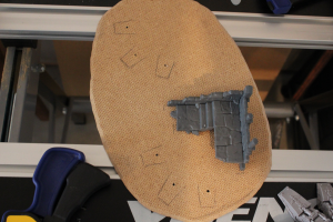
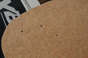
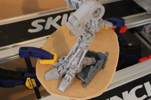
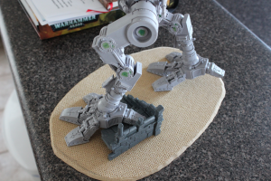
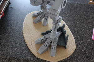
Eventually, I decided to do some screws. I could sink them into the underside of the base in such a way that it would remain flat on the bottom and still provide some additional strength. I determined to use #4 x 1/2″ flat-head wood screws. These would be short enough that they wouldn’t stick up through the top of the toes, but also long enough to provide sufficient pinning strength. I started out by setting the feet onto the base in the position I wanted them, then penciled some outlines of where the toes and the ruins went. It wasn’t perfect, but it was decent.

baseMarkingsScrewHolesTop baseScrewHolesUnderside legsPrepForScrewHoles

Continue Reading

More stuff in the Warhound building! I worked on the base a bit a few days ago. I’ve seen a few people use large cutting boards, CD/DVDs, or other stuff for their titan bases.  I wanted something bigger than a couple of CDs but not as big as a cutting board, so I decided to get some hardboard from the hardware store and cut my own base out of it. I just placed the titan’s legs onto the base and pencil-drew a rough rounded shape around the feet at about the size I wanted. After that, I cut it out with the drywall bit on my dremel, then sanded down the edges and put a bevel on it with the drum sander.

The drywall bit gave me a fairly wobbly cut around the edge I wanted (it was my first time using it, this has been a project of firsts), but I was able to sand it down to smooth enough for my purposes.  I don’t necessarily want it to look like it’s a perfectly rounded base; a little unevenness gives it a bit of a “this was torn out of the ground where the titan was walking and frozen in time” look (besides, I don’t think I can get it perfectly rounded…).

baseLeftSide baseFront

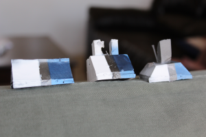
Then I did some paint tests in trying to figure out the paint scheme I want to use.

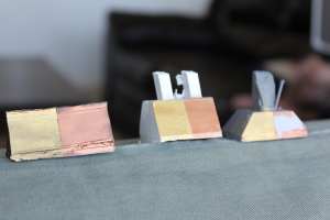
metallicBlackBlueWhitePaintTest copperBrassPaintTest

These are just some gates that I cut off the titan pieces. The one on the left is black primer, the middle is white primer, and the right one is gray primer.  In this picture I was considering doing a blue/black or a blue/white color scheme. I eventually decided on the latter, because the blue and the white are nice contrasting colors.  I’m a sucker for blue schemes, it’s always been my favorite color.

Continue Reading

Time to do the arm magnetizing. I was both excited and terrified of this part. I’ve summarized titan construction to my friends a couple of times as a series of decisions you have to make, and some of them are very hard. They’re the type of decision that if you get it right, the model looks awesome; and if you get it wrong, you may have wasted 500 GBP.

Well, figuring out the arms ended up not quite as good as I wanted it in a couple of respects (cut wasn’t quite straight, magnets not quite centered), but turned out better than I hoped in most others.

First off, on advice from the guy who runs the blog 30mm Madness, I decided to go with K&J’s stepped magnets, and went with the 1/2″ x 1/4″ thick variety. I was worried they may not fit with enough space left over in the arm joints, so I initially considered a different way of mounting the arms than the one recommended on 30mm Madness.

My plan after measuring sizes was to put one magnet inside the ball socket on the arm and hold it in with epoxy. I’d probably need to drill out a bit of the socket for the magnet with a Forstner bit. I could then sheer off the corresponding ball plug and mount the magnet in there, with the added space of the wider ball plug providing me lots of resin in which to mount the magnet. This approach would have the added benefit of having very little work if/when I ever bought additional Warhound arms. Additionally, if the cut was ugly, it would be mostly hidden by the inner part of the weapon arm’s ball socket.

The alternative, was to do it the way 30mm Madness recommends: cut the arm section with ball plugs in half, epoxy one half into the main body’s shoulder joint, and the other half into the weapon arm, with magnets mounted in each half. I had measured the width of the arm section and knew it was bigger around than the magnets, but it wasn’t by a whole lot, so I was worried I’d screw it up or there wouldn’t be enough resin to support the magnet well. The downside here is more work for new arms, the upside is that it would be significantly easier to get the angles right on the cuts. If I screwed up the cut and it was ugly, it’d be out in the open for everyone to see.

In the end, I decided to do the second approach, because I was more confident in my ability to cut straight through the middle of the ball joints than I was in my ability to get the angles right if I did the first approach.

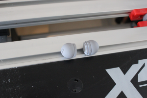
armBallsCut armyJointDrillingMagnets

Continue Reading

Been a while since I’ve updated; there have been a lot of happenings around here, and unfortunately, very few of them Titan-related.

It looks like I forgot to take pictures of the feet epoxying part.  Fortunately, it was relatively straightforward: I just put a bunch of JB weld in the joints and around the pins, then put the toes on and made sure there was plenty of it in all the sockets, then placed the foot in its posed position, and let it sit there for 24 hours to cure.  Only the left foot needed epoxying, the right foot was already pinned and superglued with the exception of one pin on the rear toe.  I just left that one upside down to cure.

Next up I epoxied the legs.  Looks like I didn’t take any during pictures of this either.  I seem to remember thinking something to the effect of it being straight-forward, so I didn’t need to take any pictures of it.  That’s irritating, because there were a lot of those situations in everyone else’s blogs that I looked at before starting my titan, and the parts that seemed straightforward to them were never straightforward to me.  And it kind of defeats the purpose of this blog a bit that I did that…

I’ll try to make up for it with description.  After mixing up the JB weld, I started in the knee joints; note that the piston on the rear of the thigh needs to be cut to size before you do this part.  If you’ve got pins in this joint, you’re not going to be able to fit the piston up into its slot after epoxying/inserting the pins.  So you need to have it measured and in place before you actually start epoxying the joints.  I had originally planned to use superglue for these because I could, but it occurred to me that while I was getting the rest of the joint in place the superglue would set before I was done, leaving me with a likely out-of-place and set piston.  No bueno, so I just decided to use JB weld on it too, which was fine; with the way the thigh pistons are slotted, it’s not going to be going anywhere once the rest of the knee joint is posed.

Doing the actual epoxying was a fairly simple matter.  Just score the inside of the joints with a sharp Xacto knife or something (provides some friction for the epoxy to grab on better) and then smear it on the inside of the joint, then repeat for the thigh piece.  I also put some down into the pin holes a bit.  However, I was using a toothpick, so I couldn’t get it that far down in there. After that, stick the pieces together, try to avoid epoxy-smearing, and then stick the pins into their holes. It turned out for me that the pins pushed a lot of their epoxy out the other end when I got them all the way in.  I used a handy toothpick to make sure they were roughly centered in their holes, wiped excess epoxy off with a paper towel, and moved on to the next joint.  Repeat for each joint on each leg.  Once that was done, I stuck them in their respective feet and left them to cure for 24 hours.  Note that the ankle joints were not epoxied yet at this point.

Once that was done, I did the hip joints and got them in their properly marked positions, epoxied and that was it.  Here’s a picture post green stuffing (which happened after).
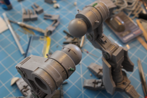
legsGreenStuffedBallsMarked

Continue Reading

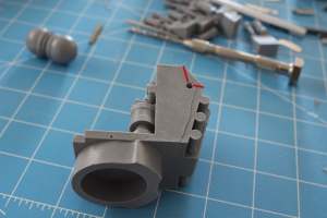
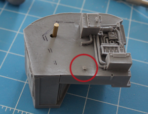
On to the main body. It took me some time to get this part figured out. A few things I noticed while doing the endless dryfitting– no really, I spent like 2 days dryfitting these before deciding exactly where to put pins as well (granted they were work days, so more like 2 evenings)– first, the sides of the back did not fit well with the middle of the back (the reactor).  I couldn’t get the boxes on the sides to fit flush with the spaces in the reactor piece.  I spent a lot of time fiddling with these and trying to find out why they didn’t fit properly.  Turns out that the side pieces have a small nub of resin sticking out that is supposed to go into the corner of the reactor piece.

mainBodyLeftNubCircled

These nubs have to be lined up properly in order for the side piece to sit flush with the side of the reactor, but when you get it lined up in the corner of the reactor room, the boxes on top and bottom don’t line up at the same time.  According to the blog linked in my last post, this is pretty common to all Warhounds.  I also discovered that the floor of the reactor was going to be very difficult to line up properly with the front of the main body.  Eventually I just decided that I was going to have to do my best and then fill in the gaps with green stuff.  I wasn’t willing to make the cuts necessary to make some of this stuff fit; and in truth I wasn’t sure it would work.  I didn’t want to cut too much and find I’d screwed up the model.

Anyway, on to the pinning.  As you can see in the above picture, I did some more sharpie marking to find pin hole positions.  I didn’t want to drill the large 1/8″ pins all the way through the body so they’d be visible from the outside, so that meant I needed to mark out the pin holes because I’d have to drill them separately. I did this by marking with the sharpie where the back edge of the reactor met the side piece.  Then, I chose a spot that looked good on the reactor piece and drilled.  From there, I used a ruler to measure how far from the corners the edge of the hole was.

reactorSideMeasurePoints

Then, with the edge markings I’d made on the side piece, I could mark the edges of the hole on it, then drill.  As you can see in the first picture, I didn’t get the location quite right on the first one.  It fit almost perfectly when it was the first hole, but once I fitted the second side piece to the reactor, the fit wasn’t as perfect.  I also found that the sides of the reactor are slanted slightly; they’re not straight up and down.  The side pieces are pretty close, so you need to decide which is going to be “flat” for your pin.  I ended up drilling more or less straight into the slanted face of the reactor piece (90 degrees perpendicular to the plane of the side where the measurements were taken).  That would put the pin poking at a downward angle into the side piece, which required a bit of a hole adjustment.  I figured no problem, the epoxy would need some space to hold the pin in.

Continue Reading
I did a fair amount of research before starting on this project.  I’d been thinking about it for several months before I finally worked up the nerve to spend the money on the model.  I’ve always dreamed of having a Titan, and now I’ve got one, I don’t want to screw it up.  I knew going into this that it would put all of my modeling skills to the test in addition to forcing me to develop new ones.  Well, so far I certainly haven’t been wrong.  I made a few mistakes, but so far I’ve been able to correct all of them (or at least mitigate them).  I’m going to include some pictures below of what I did along with my thoughts on the approach.

After doing a bunch of looking around, I decided I wanted a dynamic pose.  A straight up and down pose would be easier, but frankly, I think a lot of the flat-footed poses look kind of boring.  If this is going to be a centerpiece model for my collection, I want it to look good.  Eventually I decided that it would look really cool to have the Titan prowling through some ruins as if hunting some elusive enemy.  It took forever to find the ruins that I eventually decided to use.  I had initially planned to have it stepping onto the ruins, perhaps with the toes, but once I got some feasible ruins, I found that it was not likely to be a natural-looking pose with just the toes on the piece, so I decided I’d have the Titan stepping over the ruins as if it were just putting its heel down on the other side of a smashed wall.  The ruins come from GW’s Ruins of Osgiliath set.  I’m only using one of the pieces right now; the rest are either going to end up on the base or on my table as terrain.

So, first things first: get the feet done.  Starting with the left foot, I spent a ton of time dry fitting (not kidding here, I spent like 2 days dry fitting and trying different poses) for just the foot.  I used a bit of poster sticky-tac (not sure if that’s the real name or just what everyone around here calls it) to hold bits in position.

leftLegAssembledPins

Continue Reading