On to the main body. It took me some time to get this part figured out. A few things I noticed while doing the endless dryfitting– no really, I spent like 2 days dryfitting these before deciding exactly where to put pins as well (granted they were work days, so more like 2 evenings)– first, the sides of the back did not fit well with the middle of the back (the reactor). I couldn’t get the boxes on the sides to fit flush with the spaces in the reactor piece. I spent a lot of time fiddling with these and trying to find out why they didn’t fit properly. Turns out that the side pieces have a small nub of resin sticking out that is supposed to go into the corner of the reactor piece.
These nubs have to be lined up properly in order for the side piece to sit flush with the side of the reactor, but when you get it lined up in the corner of the reactor room, the boxes on top and bottom don’t line up at the same time. According to the blog linked in my last post, this is pretty common to all Warhounds. I also discovered that the floor of the reactor was going to be very difficult to line up properly with the front of the main body. Eventually I just decided that I was going to have to do my best and then fill in the gaps with green stuff. I wasn’t willing to make the cuts necessary to make some of this stuff fit; and in truth I wasn’t sure it would work. I didn’t want to cut too much and find I’d screwed up the model.
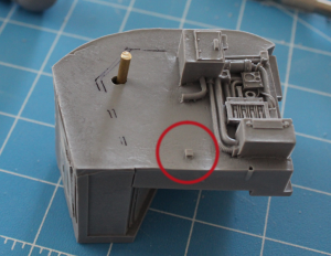
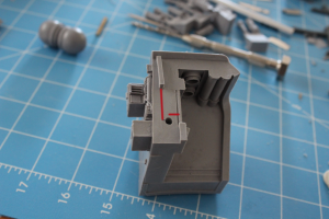
Anyway, on to the pinning. As you can see in the above picture, I did some more sharpie marking to find pin hole positions. I didn’t want to drill the large 1/8″ pins all the way through the body so they’d be visible from the outside, so that meant I needed to mark out the pin holes because I’d have to drill them separately. I did this by marking with the sharpie where the back edge of the reactor met the side piece. Then, I chose a spot that looked good on the reactor piece and drilled. From there, I used a ruler to measure how far from the corners the edge of the hole was.
Then, with the edge markings I’d made on the side piece, I could mark the edges of the hole on it, then drill. As you can see in the first picture, I didn’t get the location quite right on the first one. It fit almost perfectly when it was the first hole, but once I fitted the second side piece to the reactor, the fit wasn’t as perfect. I also found that the sides of the reactor are slanted slightly; they’re not straight up and down. The side pieces are pretty close, so you need to decide which is going to be “flat” for your pin. I ended up drilling more or less straight into the slanted face of the reactor piece (90 degrees perpendicular to the plane of the side where the measurements were taken). That would put the pin poking at a downward angle into the side piece, which required a bit of a hole adjustment. I figured no problem, the epoxy would need some space to hold the pin in.
Same issue and procedure for the other side.
You can see on the first picture where I had to readjust the lines to after fitting the pin for this side piece. It took a while and was irritating, but wasn’t much of an actual problem because I had a lot of resin space to work with and the additional hole space could be filled with the JB Weld.
Once I was satisfied with those pieces, I moved on to attaching the front. I decided to use one 1/8″ pin for each side rather than multiple smaller pins. Since I only had 1.25mm pins (other than the 1/8) I thought I would probably need 3 or 4 per side, and that was a lot more drilling in space I probably didn’t have than I wanted to do.
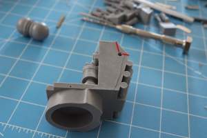
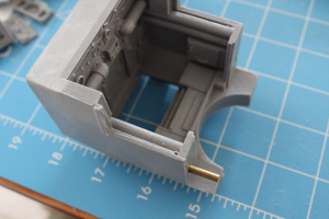
These pins were drilled so that they went into the boxes along the side of the front, nicely hiding the work when the model was built. Same procedure here. I drilled in the front piece first, then measured for where to put it on the rear side pieces. A couple of things to note: measuring from the side was easy since it fit flush with the edges of the side pieces. Measuring vertically was another matter. The bottom of the rear sides did not sit flush with the top of the waist-hole-area on the front. However, the side pieces do have a nub sticking out on the front that sat flush with the top of the front. I decided to measure from the top of that face on the front, and line that up with the bottom of the long nub on the side pieces, and that worked out really well. You can see one of the holes here; I’ve marked the lengths I measured.
This time I decided to try to measure the center of the hole, since that seemed to be easier to get right. Got the pins lined up due to the measuring with very few issues. However, after I had all the main pins in and the big pieces dryfitted, I noticed that I had a gap between the floor of the reactor piece and the floor of the front piece. I determined that the pin on one side wasn’t quite in the right position, so I ended up widening it a bit (first picture) and that’s why it looks like it’s been totally redrilled to the side. I still wasn’t able to get the gap to go away completely, but I was able to minimize it a bit so that I could fill it with green stuff later.
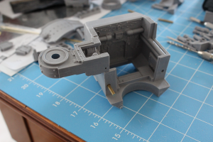
That done, I put a couple of 1.25mm pin holes into the bottom of the side pieces from the outside into the floor of the reactor piece. Went perfectly on one side, and on the other I had to drill 3 holes before I finally got one that was mostly lined up (that’s why you can see the bulged out pin spot along the bottom in the first picture). I’m not too worried about this; it’s essentially blocked by the front when it’s all together so it’s close to invisible and the extra holes will have to be filled with green stuff. I wasn’t pleased with the number of tries it took, but it was fairly easy to repair later.
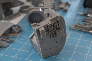
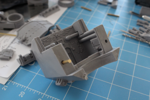
Next up, I pulled the thing apart and got to work on the shoulder pieces. I only had room to do the 1.25mm pins in these ones, and decided to drill down at an angle into the front piece’s wall.
The pin went in well kind of between the cable and the actual wall of the front piece. You can see the same thing on the opposite side, although the angle in the picture’s not great.
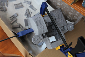
After that I got down to the business of epoxying. I didn’t take any pictures of this step; just one of the after-the-fact clamping. Before doing the actual epoxying, I went through and “wobbled” the drill bit through each of the holes to make additional room for the epoxy. Before the wobbling the drilled holes were pretty tight against the pins. After that was done, I rewashed all of the pieces involved, both to get off resin dust that had accumulated and to remove some extra release agent that I hadn’t gotten off in my first washing. I used some dish soap and an old soft-bristle toothbrush. Got it all off and let it air dry; didn’t take too long, but left it to dry overnight.
I used JB Weld because I had some experience before repairing an airsoft gun, and know it to be very strong. Even though I had large pins here for supporting the weight, I’d had some bad experiences with using superglue on the toes, so I wanted to avoid that this time as well. All in all, using a slow-drying epoxy that would be stronger than superglue was the way to go for me. Since this is my first project doing pinning, I need some extra time to get the pins situated the right way, and the JB Weld gives me that.
Anyway, I got the epoxy in all the pin holes, with the extra space working well to provide room for the JB Weld to go in and hold the pin there. All of my 1/8″ pins were precut with a Dremel. The pin is too thick for me to properly cut it with the clippers I have (I actually put a couple of small notches in my nice very sharp wire clippers. Was not pleased). Once the epoxy was all in, I clamped it and left it for 24 hours to cure. The clamping was necessary because the epoxy will tend to contract in certain places, forcing expansion in others. With the clamps, I could control the major axes of the body and make sure that didn’t happen.
Next up, some additional posing on the legs, and epoxying the feet and leg joints.
